The need for high accuracy and complex designs in various industries has led to the evolution of modern CNC machining. Gaining proficiency in 5-axis programming has become crucial for engineers and machinists alike, as competitive manufacturing places a premium on automation, speed, and accuracy. If you’re wondering how to create 5 axis program, this guide will provide step-by-step instructions to streamline the process.
What is 5-Axis CNC Machining?
5-axis machining adds two rotational axes: A (tilting the tool or table) and B or C (turning around the X, Y, or Z axis), in contrast to conventional 3-axis machining, which works along the X, Y, and Z axes. As a result, the cutting tool can reach the workpiece from almost any direction. Capabilities are where the main distinctions lie: 5-axis machines are excellent at complex shapes, enabling higher precision, fewer setups, and the capacity to create complex parts in a single operation, whereas 3-axis machines are restricted to simpler geometries.
Prerequisites for Creating a 5-Axis CNC Program
Before diving into 5-axis programming, ensure the following essentials are in place:
- Understand the Part Design & Tolerances
A deep understanding of the part geometry, critical features, and tolerances is key to planning effective toolpaths. - Select the Right CAM Software
Use advanced software like Autodesk PowerMill that supports full 5-axis strategies and offers robust simulation tools. - Import Accurate CAD Models
Begin with high-quality CAD models to avoid geometry issues that could impact machining precision. - Ensure Machine Compatibility & Post-Processor Availability
Confirm your CNC machine supports 5-axis operations and has a verified post-processor tailored to your setup.
How to Create 5 Axis Program: Step-by-Step Guide
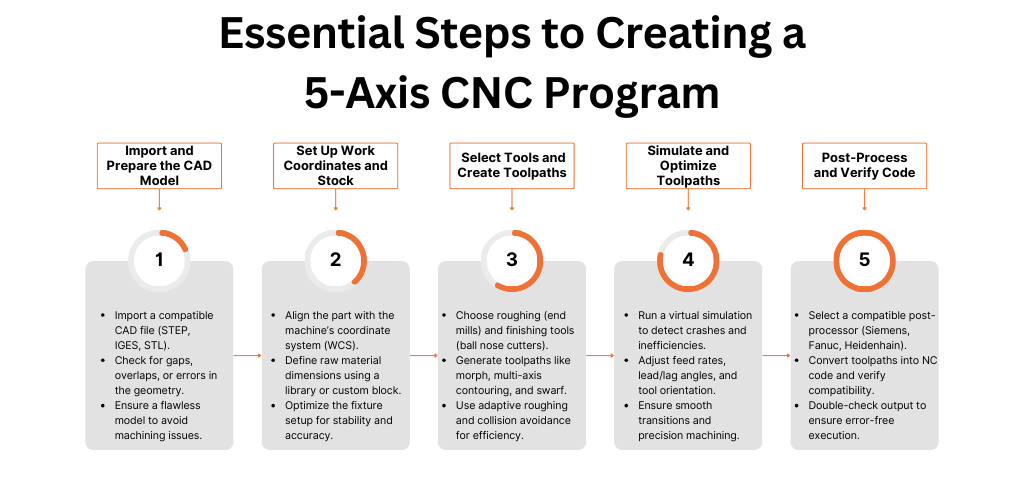
Step 1: Import the CAD Model
Your CAD file should first be imported in a compatible format, like STEP, IGES, or STL. Make sure the geometry is free of any gaps or overlapping surfaces that could interfere with machining. Early correction of design problems is crucial since a perfect model lays the groundwork for success.
Step 2: Set Up the Work Coordinate System (WCS)
Set the WCS so that the part aligns with the coordinate system of the machine. Taking into account the fixture arrangement and the features of the part, select an orientation that maximizes multi-axis toolpaths. Accuracy is improved, and repositioning is reduced with proper alignment.
Step 3: Define Stock and Tool Library
Choose from a library or create a custom block to specify the dimensions of the raw material. Next, add tools for roughing (like end mills), semi-finishing, and finishing (like ball nose cutters) to your tool collection. For optimal results, match the tools to the shape and material.
Step 4: Create Toolpaths
Make toolpaths that are specific to 5-axis machining, including morph for seamless transitions, multi-axis contouring for edges, or swarf for sidewalls. Understanding how to create 5 axis program involves selecting the right toolpaths that ensure smooth machining and high precision. Utilize tool axis control to maintain accuracy and collision avoidance features to safeguard the tool and workpiece. Unlike conventional techniques, adaptive strategies for roughing remove material effectively without overtaxing the tool.
Step 5: Toolpath Simulation
To identify possible crashes or inefficiencies, simulation is essential. After visualizing the tool’s path through a virtual machining session, adjust variables such as feed rates, lead/lag angles, and tool orientation. This step ensures quality and safety before the software reaches the machine.
Step 6: Post-Process the Code
Choose a post-processor (such as Siemens, Fanuc, or Heidenhain) that works with the controller of your machine. This converts your toolpaths into executable NC code. A crucial step in learning how to create 5 axis program is ensuring that the post-processed code aligns with the machine’s specifications to avoid errors during execution. Verify the output again to make sure it complies with the requirements of your equipment.
Pro Tips for Efficient 5-Axis Programming
- Ease In: Before attempting full simultaneous 5-axis motion, begin with 3+2 axis machining (fixed-angle placement).
- Tool Length: To reduce deflection and increase stability, use shorter tools.
- Kinematics: When designing toolpaths, consider the pivot points and rotary restrictions of your machine.
- Verification: Utilize third-party tools (like Vericut) and backplotting to properly validate toolpaths.
Common Mistakes to Avoid
Avoid issues like over-pressurising the machine, which could cause mechanical failure, or improperly orienting the tool, which could gouge the part. For simple geometries, keep toolpaths simple; efficiency is just as important as accuracy.
Final Checklist Before Running the Program
- Verify that tool offsets and lengths are set appropriately in the machine.
- The CNC machine should be warmed up and adjusted to operational conditions.
- Run a dry test (without material) to identify any problems.
- Inform the operator about the safety procedures and the characteristics of the program.
Final Insights
Importing a CAD model, configuring coordinates, specifying tools and stock, creating accurate toolpaths, simulating, and post-processing are all necessary steps in creating a 5-axis CNC program. Mastering how to create 5 axis program requires continuous learning, practice, and attention to detail, ensuring efficiency and accuracy in machining processes. Gaining proficiency in this powerful method opens up new production opportunities with each stage. Examine software samples, video tutorials, or community resources from Autodesk for additional learning.
Are you prepared to advance your CNC machining skills? For professional Autodesk PowerMill and FeatureCAM training, individualized consultancy, and accuracy-driven software solutions, get in contact with Mechman Solution.
To schedule a free demo or training consultation, get in touch with us right now.
📩 mechmansolution@gmail.com | 📞 +91 99137 89065 | 🌐 www.mechmansolution.com
Also Read: Why PowerMill And FeatureCAM Are Among The Best CAD CAM Software In India?