SCAN
→ CAD
🔍 Reverse Engineering Guide — WinFusion 2025
Reverse Engineering Kya Hai? —
Physical Part Se CAD Model aur CNC Program! 🔍
3D Scan | Point Cloud | Surface Fit | CAD Rebuild | CAM Programming | WinFusion Role
RE Complete Flow:
Physical Part ⭐
→
3D Scan
→
Point Cloud
→
CAD Rebuild ⭐
→
CAM → CNC ✅
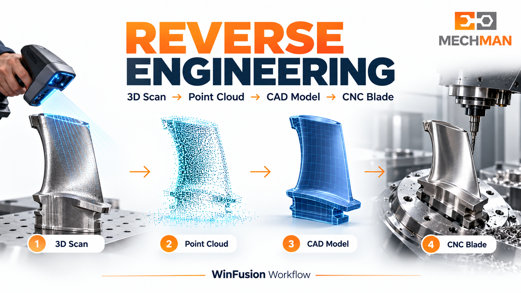
Reverse Engineering = physical part se start karke digital model banana aur phir CNC program se us part ko manufacture karna. Legacy parts, worn tooling, no-drawing components ya design improvement — sab mein RE use hota hai!
Drawing nahi hai, original manufacturer nahi mila, lekin machine part reproduce karna hai? Ye Reverse Engineering ka classic scenario hai! Physical part → 3D scan → point cloud → surface fitting → CAD model → CAM → CNC! WinFusion is chain ke manufacturing execution stage mein directly fit hota hai — CAD model ready hone ke baad CAM programming, simulation, post processor aur machine trial tak!
“Reverse Engineering aur remanufacturing mein critical accuracy requirement yeh hai: Reproduced part ka final inspection original drawing ya reference part se compare kiya jaata hai — CAD model kitna accurate tha iska practical answer yahin milta hai!” ✅
WinFusion ka RE contribution: Jab CAD model ready ho — CAM setup, tool library, machine simulation, post processor aur implementation support! 3D scan aur mesh-to-CAD conversion ke liye dedicated RE software (Geomagic, PolyWorks, etc.) alag hote hain! ✅
🔍 Reverse Engineering Kab Use Hota Hai? — 4 Real Scenarios!
Ye 4 scenarios mein CNC manufacturers ko RE ki zaroorat padti hai:
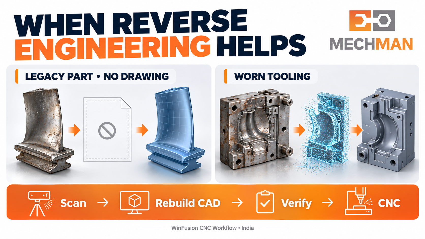
RE scenarios: Legacy part, worn tooling, design improvement, competitor analysis — sab alag purposes hain. CNC shop ke liye sabse common = legacy spare part aur jig/fixture reproduction!
Original OEM discontinued, drawing nahi — lekin machine ka critical component reproduce karna hai. Scan → CAD → CNC!
Production fixture worn ho gayi. Original drawing nahi — good fixture scan karo, CAD banao, new fixture machine karo!
Existing part ko improved material ya geometry ke saath re-design karna. Scan se baseline → engineering team modify → updated CAM!
4
Mould / Pattern Digitise
Physical mould ya pattern ko CAD mein capture karo — machining ya inspection ke liye digital reference banao!
⚙️ Reverse Engineering — 5-Step Complete Workflow!
1
Physical Part Ki 3D Scanning ⭐⭐
CMM, structured light scanner, laser scanner ya handheld scanner se part ko measure karo. Result = dense point cloud — thousands ya millions of measured points jahan part ki surface thi!
Scanner types:
CMM, laser scan, structured light, photogrammetry
Output: ⭐
Point cloud — XYZ coordinates of surface!
2
Point Cloud Processing — Mesh Banana ⭐
Point cloud ko clean karo — noise, outliers remove. Phir points se polygon mesh (triangulated surface) create karo. RE specialist software (Geomagic, PolyWorks) yahin use hoti hai!
Mesh quality scanning accuracy aur software processing par depend karti hai! ⭐
3
CAD Rebuild — Surface Fitting & Solid Model ⭐⭐
MOST CRITICAL
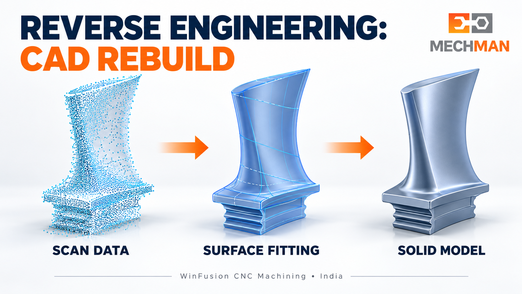
RE critical step: Polygon mesh se solid CAD model banana. Simple parts = feature extraction. Complex organic surfaces = NURBS fitting. Accuracy mesh quality, fitting tolerance aur engineer skill par depend hai!
Simple parts:
Planes, cylinders, slots → parametric features extract karo
Complex surfaces: ⭐⭐
Blade, impeller, mould → NURBS fitting! Expert work!
4
CAD Quality Check & Inspection ⭐⭐
Rebuilt CAD model ko original scan se compare karo — deviation map generate karo. Critical dimensions, tolerances aur surface accuracy verify karo. This step is NON-NEGOTIABLE!
Deviation map ⭐
Tolerance check
Surface accuracy ⭐⭐
Approve karo ✅
5
WinFusion: Approved CAD → CAM → CNC Production! ⭐⭐ 🚀
WinFusion HERE!
Approved CAD model se WinFusion workflow begin hota hai — CAM setup, stock, WCS, toolpath, machine simulation, collision check, proven post processor, NC code → CNC trial → production!
CAM Setup
→
Toolpath ⭐
→
Machine Sim ⭐⭐
→
Proven Post ⭐⭐
→
NC → CNC ✅
🌀 Turbine Blade RE Example — Step by Step!
Old turbine blade — no drawing available — reproduce karna hai. Real workflow:
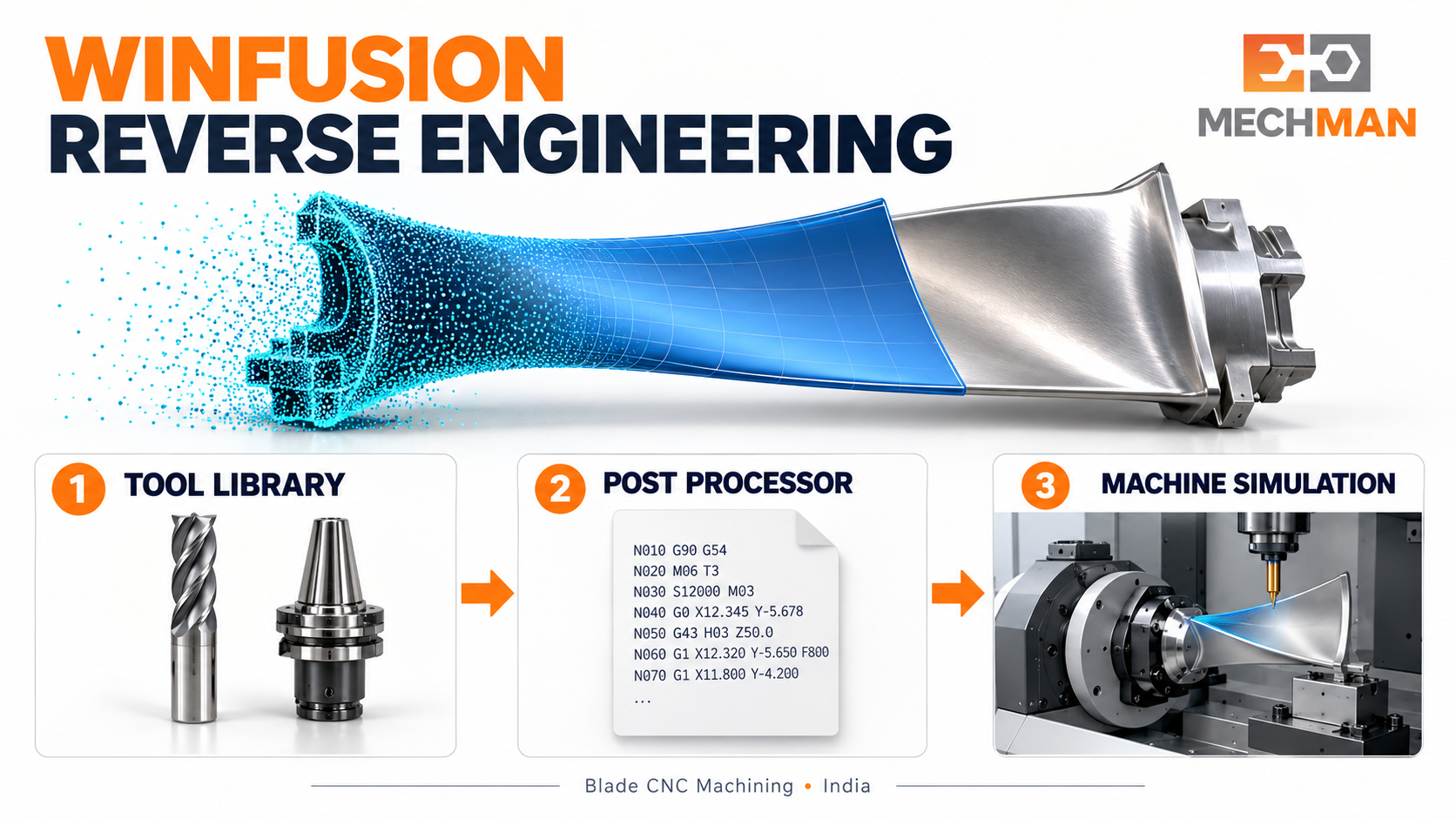
Turbine blade RE: 3D scan → point cloud → mesh → NURBS surface fit → solid CAD → WinFusion CAM → blade toolpath + holder clearance simulation → proven post → NC → 5-axis CNC trial!
1
Blade structurally sound confirm karo — scan karo (laser/structured light) ⭐
2
RE software mein point cloud clean → airfoil surface NURBS fit karo ⭐⭐
3
CAD model inspect → deviation check → tolerance approval ⭐⭐
4
WinFusion: CAM toolpath + 5-axis tool orientation + holder clearance simulation ⭐
5
Machine-specific post → NC code → 5-axis CNC trial run ⭐⭐
6
First blade inspect → original reference compare → approve → production! ✅
⚠️ RE Accuracy — 4 Critical Points!
Scan ≠ Perfect Copy: ⭐
Scan noise, surface damage, wear — model accuracy par impact karte hain!
NURBS Fitting Expertise: ⭐⭐
Complex blade, impeller surfaces ke liye expert RE specialist needed!
Inspection Non-Negotiable: ⭐⭐
Reproduced part → original reference se CMM ya scan se compare karo!
IP / Legal: ⭐
Competitor product RE karna intellectual property concern raise kar sakta hai!
Reverse Engineering → WinFusion CNC Production! 🔍
Physical part se scan, CAD model rebuild, inspection — aur phir WinFusion se CAM, simulation, post, NC aur CNC production tak complete RE-to-manufacturing chain!
WinFusion: Approved RE Model + CAM + Tool Library + Simulation + Proven Post + Trial = RE to CNC Production! 🔍🚀
🔍
Reverse Engineering | CAD Model | CAM | Simulation | Post Processor
Physical part, scan data ya approved CAD model share karein — CAM implementation discuss karein!
Mechman Solutions — WinFusion
Autodesk Authorized Partner | Vadodara, Gujarat | Since 2015
www.mechmansolution.com
© 2025 Mechman Solutions | WinFusion — Reverse Engineering & CNC Manufacturing Guide | Vadodara, Gujarat